-
SERVICES
- Gravity » AIRGrav
- Marine AIRGrav
- Magnetic Total Field
- Magnetic Gradient
- Radiometrics
- Frequency-Domain EM
- Geoid Applications with AIRGrav
- Scanning LiDAR
- Methane Sensing
- Multi-Parameter Surveys
- Environmental Monitoring
- Baseline Monitoring & Contamination Detection
- Data Interpretation
- Navigation » SGNav
- Drape Flying » SGDrape
- Quality Control
 |
|---|
 |
 Scanning LiDAR for Terrain MappingSander Geophysics Ltd (SGL) provides terrain mapping services using a sophisticated airborne scanning LiDAR (Light Detection and Ranging) system, which collects data along a swath below the aircraft flight path, using a Riegl LMS-Q280i airborne laser scanner. The scanning LiDAR data are geometrically corrected with accurate GPS location, and pitch, roll and yaw determinations. Other geophysical information, such as AIRGrav or aeromagnetic data, is collected simultaneously using SGL´s fixed-wing and helicopter platforms. The scanning LiDAR system allows SGL to produce high resolution digital terrain models which can be used for environmental assessment, geotechnical and engineering applications as well as gravity terrain corrections. SGL has used laser scanner data since 1998 in order to provide its clients with the most accurate terrain elevation data possible. The laser wavelength of SGL's scanning LiDAR system is near infrared and the scanning mechanism is a rotating polygon mirror which provides the laser measured distance and the 24-bit RGB colour of the target's surface. This allows SGL to provide a digital colour image of the ground surface along with the digital elevation model, and any other geophysical data collected. The GPS position recovery uses NovAtel dual frequency receivers in the aircraft and on the ground, processed using SGL's proprietary GPSoft processing system, resulting in a horizontal position accuracy of better than 0.2 m and a vertical position accuracy of better than 0.3 m. The aircraft attitude (pitch, roll, and yaw) can be provided using SGL's AIRGrav system at a data rate of 128 samples per second, and an accuracy of better than 0.5 arcmin for pitch and roll measurements and 1.0 arcmin for yaw. 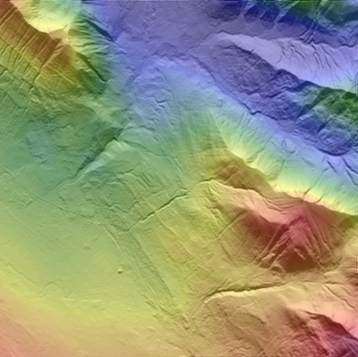
Figure 1: Scanning LiDAR digital terrain model with magnetic data superimposed A "bare-earth" digital terrain model, in which the effects of vegetation are removed, can be generated through the application of an iterative process. An example is shown below. 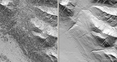
|
||||||||||||||||||||||||||||||||||||||||||||||||||||||
Basic Specifications of the Scanning LiDAR System
|
||||||||||||||||||||||||||||||||||||||||||||||||||||||